Page review information
Edition covered
NFPA 79 / IEC 60204-1 / IEC 60445 (conductor identification) — NFPA 79:2024; IEC 60204-1:2016+AMD1:2021
Content status
Reviewed
Coverage
15 reference diagrams across machinery, facility, control, instrumentation, motion, HVAC, semiconductor and network wiring
Last reviewed
August 2026
Primary reference
The official published standard — required for final decisions

Confirm the governing edition, jurisdiction, and project-specific requirements before applying anything on this page.

⚠ These diagrams are engineering examples, not a code citation. Local code, the authority having jurisdiction, your customer’s standards, and the project drawings take precedence over everything on this page — in that order. Colour conventions vary by jurisdiction, by industry, by customer, and by the age of the installation. Nothing here overrides a drawing. Verify against the governing standard and the as-built documents, and test before you touch a conductor.

Why colour is a safety control, not decoration

Colour is the fastest signal a panel gives you, and it is the one people trust before they trust anything else. That is exactly what makes it dangerous when it is wrong or inconsistent.

Two of the rules below are the ones that actually hurt people:

Everything else is convention in service of traceability. Colour narrows down what kind of circuit you are looking at; the wire number and the drawing tell you which circuit it is. Colour alone has never been enough, which is why every diagram below is paired with the same refrain: label both ends, and match the schematic.


1. Reference standards
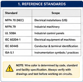
Table of the standards governing conductor identification: NFPA 70 (NEC) for US electrical installations, NFPA 79 for industrial machinery, UL 508A for industrial control panels, IEC 60204-1 for electrical equipment of machines, IEC 60445 for conductor and terminal identification, and ISA-5.1 for instrumentation symbols. A note warns that wire colour is determined by code, standard and facility specification, and that circuits must always be verified against drawings and tested before work.
The documents that actually decide the colour — and the reminder that facility specifications sit on top of them.

2. Machinery and facility power

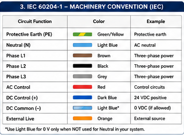
The two machinery conventions differ in almost every conductor except protective earth. A machine built to one and shipped to a market expecting the other is a recurring source of confusion — see the NFPA 79 ↔ IEC 60204-1 crosswalk.
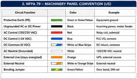
NFPA 79 machinery panel colour convention table: protective earth green or green-with-yellow stripe; ungrounded AC or DC power black; AC control at 120/230 VAC red; DC control at +24 VDC blue; DC common at 0 VDC white with blue stripe; AC neutral white; external live circuits that stay energised orange; external neutral white with orange stripe; bonding jumper green-and-yellow.
NFPA 79 (US machinery). Black power, red AC control, blue DC control — and orange for anything that stays live when the disconnect is off.
IEC 60204-1 machinery colour convention table: protective earth green-and-yellow; neutral light blue; phase L1 brown, L2 black, L3 grey for three-phase power; AC control red; DC control positive dark blue; DC common light blue, with a footnote that light blue is used for 0 V only when it is not already used as the neutral in the system; external live orange.
IEC 60204-1 (international machinery). Brown/black/grey phases, light blue neutral — and the light-blue collision to watch: it cannot be both neutral and DC common in the same system.
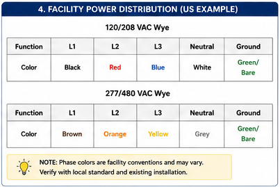
US facility power distribution phase colour table. For 120/208 VAC wye: L1 black, L2 red, L3 blue, neutral white, ground green or bare. For 277/480 VAC wye: L1 brown, L2 orange, L3 yellow, neutral grey, ground green or bare. A note states that phase colours are facility conventions that may vary, and must be verified against the local standard and the existing installation.
US facility distribution. Note the honest caveat on the diagram: outside the grounded and grounding conductors, these phase colours are convention, not code — verify against the existing installation.

The 480 V orange trap. In the US facility convention above, orange is the L2 phase of a 277/480 V system. In the NFPA 79 machinery convention, orange means externally-supplied and still live with the disconnect off. Same colour, two entirely different warnings, and a machine panel fed from a 480 V facility can contain both. This is precisely why colour is never sufficient on its own — the wire number and the drawing resolve it.


3. PLC and control circuits
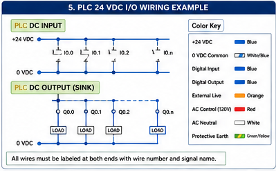
PLC 24 VDC input and output wiring example. DC input section shows sensors wired from a +24 VDC rail through input points I0.0 to I0.n returning to 0 VDC. DC output section shows sinking outputs Q0.0 to Q0.n driving loads referenced to 0 VDC. A colour key gives: +24 VDC blue, 0 VDC common white with blue stripe, digital input blue, digital output blue, external live orange, AC control 120 V red, AC neutral white, protective earth green-and-yellow. A note states all wires must be labelled at both ends with wire number and signal name.
PLC 24 VDC I/O. Blue for the DC control circuit, white-with-blue-stripe for the 0 V common — and the note that matters more than any of the colours: label both ends.
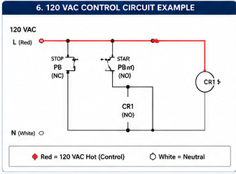
120 VAC control circuit example showing a standard start/stop seal-in circuit. A red 120 VAC hot conductor labelled L feeds a normally-closed STOP pushbutton in series with a normally-open START pushbutton, with a normally-open CR1 auxiliary contact wired in parallel across the START button to seal the circuit in, driving relay coil CR1 back to a white neutral conductor labelled N. Key: red is 120 VAC control hot, white is neutral.
120 VAC control. The seal-in circuit every panel has: red hot through stop-then-start, CR1 latching itself, white back to neutral.

4. Instrumentation and intrinsically safe circuits
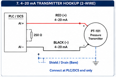
Two-wire 4 to 20 mA transmitter hookup. A PLC or DCS analog input card supplies loop power from its AI+ terminal on a red positive conductor to the positive terminal of pressure transmitter PT-101, returning on a black negative conductor to AI−, with a 250 ohm sense resistor shown across the analog input. The cable shield or drain wire is shown dashed and connected at the PLC/DCS end only.
4–20 mA, 2-wire. Red positive, black negative, and the shield landed at one end only — see the 4–20 mA loop guide for the burden budget behind it.
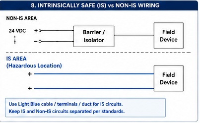
Intrinsically safe versus non-intrinsically-safe wiring. In the non-IS area, a 24 VDC supply feeds a barrier or isolator, which then feeds a field device. In the IS area, a hazardous location, the conductors from the barrier to the field device are drawn in light blue. A note states to use light blue cable, terminals and duct for IS circuits, and to keep IS and non-IS circuits separated per standards.
Intrinsically safe circuits. Light blue is the IS marking convention — and the separation from non-IS circuits is the actual safety requirement, not the colour.

Light blue is overloaded. It is the IEC neutral, it is an IEC DC common, and it is the intrinsic-safety marking colour. Which one it means depends on the system you are standing in front of. In an IS installation, treat light blue as IS and do not reuse it for anything else.


5. VFD, servo and motion systems
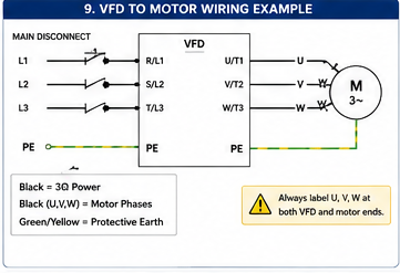
VFD to motor wiring example. Three-phase supply L1, L2, L3 passes through a main disconnect to VFD input terminals R/L1, S/L2, T/L3. VFD output terminals U/T1, V/T2, W/T3 feed motor terminals U, V, W on a three-phase motor. A green-and-yellow protective earth conductor runs from the disconnect through the VFD to the motor. Key: black is three-phase power, black U V W are the motor phases, green-and-yellow is protective earth. A warning states to always label U, V and W at both the VFD and motor ends.
VFD to motor. Phase sequence is the whole point of labelling U/V/W at both ends — swap two and the motor runs backwards. See the VFD wiring guide for cable and shielding practice.
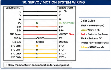
Servo drive to servo motor wiring. Power conductors U, V, W run from drive to motor, with a green-and-yellow protective earth. A holding brake pair BR+ and BR− is shown in red. Encoder power at +5 V or 24 V, encoder 0 V, and encoder data run as twisted pairs. Four STO channels, STO1+, STO1−, STO2+ and STO2−, are shown in yellow. Colour guide: black is power U V W, green-and-yellow is PE, red is brake plus and encoder power, black is brake minus and 0 V, twisted pair is encoder data, yellow is STO channels. A note says to follow manufacturer documentation for the exact pinout.
Servo and motion. Power, brake, encoder and STO in one cable run. The note is the important part — the manufacturer's pinout wins; servo colour conventions are far less standardised than machinery power.

6. HVAC and semiconductor facilities
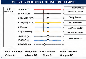
HVAC and building automation wiring example from an air handling unit controller to field devices. Conductors shown: 24 VAC hot in red, 24 VAC common in black with blue, analog input 0 to 10 V signal in white, analog output 0 to 10 V signal in yellow, digital input status in blue, digital output command in orange, RS-485 A positive and RS-485 B negative as a pair, and a shield or drain. Field devices listed are actuator/valve, temperature sensor, VFD speed reference, fan proof switch, damper actuator and BMS network.
HVAC / building automation. A different world with its own conventions — 24 VAC rather than 24 VDC, and signal type encoded by colour.
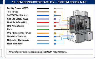
Semiconductor facility system colour map showing colour-coded connections into a process tool: facility power at 480 V, tool power, 24 VDC tool control, gas life safety (GLS), fire life safety (FLS), FMS monitoring, BMS, UPS and emergency power, controls network, corporate network, and fibre backbone. A note states to always follow site standards and tool OEM requirements.
Semiconductor fab. Life-safety systems (GLS, FLS) get their own identity precisely so they cannot be confused with tool control. Site standards and the tool OEM govern — see the semiconductor section.

7. Industrial networks

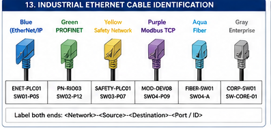
Industrial Ethernet cable identification by jacket colour: blue for EtherNet/IP, green for PROFINET, yellow for a safety network, purple for Modbus TCP, aqua for fibre, and grey for the enterprise network. Each patch cable carries an example label pair such as ENET-PLC01 / SW01-P05. A note gives the labelling convention: label both ends with network, source, destination, and port or ID.
Network cables. Yellow for the safety network is the one that earns its keep. The label convention below the cables — network, source, destination, port — is what makes a patch field traceable.
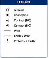
Legend for the symbols used across these diagrams: terminal, connection, normally-open contact, normally-closed contact, wire, shield or drain shown as a dashed line, and protective earth.
Symbol legend for the diagrams on this page.

8. Field notes

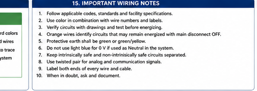
Ten important wiring notes: follow applicable codes, standards and facility specifications; use colour in combination with wire numbers and labels; verify circuits with drawings and test before energising; orange wires identify circuits that may remain energised with the main disconnect off; protective earth shall be green or green-and-yellow; do not use light blue for 0 V if it is used as neutral in the system; keep intrinsically safe and non-intrinsically-safe circuits separated; use twisted pair for analog and communication signals; label both ends of every wire and cable; when in doubt, ask and document.
The ten rules the rest of this page is a long-form argument for. (The source graphic carries a small sliver of an adjacent panel on its left edge — a cropping artifact in the original, not a missing diagram.)

Working on an existing panel that follows none of this? That is the normal case, not the exception. Do not “fix” the colours on a live system as a side quest — you will strand the next person between the panel and a drawing that no longer matches it. Record what is actually there, mark up the drawing, and change the wiring and the documentation together, as a controlled change.


Standards references

Standard What it governs here
NFPA 79 Conductor identification for the electrical equipment of industrial machinery (US)
IEC 60204-1 Conductor identification for the electrical equipment of machines (international) — Clause 13 wiring practices, Clause 16 marking and reference designations
NEC (NFPA 70) Grounded and grounding conductor identification in US installations. Phase colours are largely facility convention, not code
IEC 60445 Identification of conductors and terminals
UL 508A Industrial control panel construction

Colour conventions are not reproduced from the standards’ tables here — the diagrams are original illustrations of widely-taught practice. For any binding requirement, consult the published standard and your governing code.

← Back to Wiring & Installation Guides

Trust Boundary — Engineering Judgment Required

This site is an independent educational reference for industrial automation standards. It paraphrases and organizes guidance in original language; it is not a substitute for the official published standards, professional engineering judgment, or legal review, and content has not been independently verified against current published editions.

Items marked Review pending await technical review against the identified edition. Items marked Planned have no reviewed source material behind them. Do not rely on this site for compliance determinations, safety-critical design decisions, or legal interpretation.